UrbanWeave - MFA Thesis
UrbanWeave (working title) is a procedural city generator I’ve been working on since September 2024. Current procedurally generated city engines either create a homogeneous product with no individual districts with unique character. To remedy this I will use an intelligent decision algorithm and generated data to simulate zoning and historic growth.
v0.7.05 05-12-25
This update streamlines the way road endpoints (“tips”) are found and operated on by separating data gathering from decision-making and execution. Instead of processing each tip in place, the script first collects all tips, along with their positions, levels, and types, into arrays. This lets the logic run over a clean snapshot of tip data, avoiding costly repeated geometry lookups and in‐flight mutations.
A new getConn() helper function replaces the old nested loops for finding all points connected to a given tip. By turning that traversal into a reusable function, the code is not only much easier to read but also guarantees that tips will only consider truly unconnected candidates. Proximity checks now scale with road hierarchy—smaller roads use a finer merge radius, while larger roads can reach farther—ensuring that merging feels natural at every level without manual tweaking.
When a valid neighbor is identified, the script no longer writes changes immediately. Instead, it queues up modifications—new midpoints, endpoint collapses, attribute updates—in temporary lists. Only after every tip has been evaluated does a final pass apply those updates in one go. This separation of evaluation and application not only prevents hidden bugs from unexpected geometry mutations but also dramatically improves performance on dense networks.
Taken together, these refactors reduce redundant work, make the flow of logic far more transparent, and lay the groundwork for adding more sophisticated connection rules or visualization aids in the future. By embracing a batch-oriented, function-driven structure, the road network generator is now both easier to maintain and far better equipped to scale as complex urban layouts or terrain constraints are introduced.
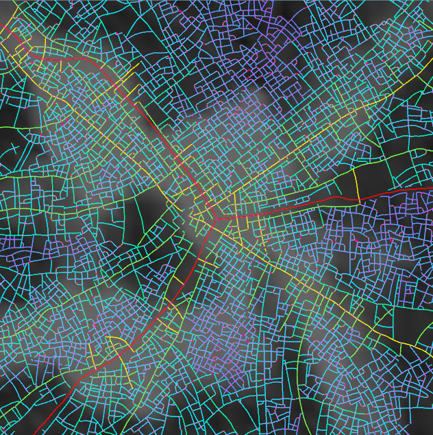
Additionally, I added a feature that allows the algorithm to read terrain data, specifically a terrain map and water mask image. It can display the height, though currently it has no effect on the road network.


v0.7.04 05-05-25
Continuing development on the intersection geometry system, v0.7.04 marks a major optimization milestone. One of the primary goals for this update was improving performance and scalability. Previously, the program would slow to a halt when handling around 40 intersections, mainly due to inefficient variable access and repeated logic calls. To address this, I restructured the system to first gather all necessary data into arrays before performing any logic operations. This reduced redundant computation and significantly improved performance.
Another structural improvement involved reorganizing the road key identifiers. Originally, I used lowercase letters (l, w, c, e) to denote lane width, sidewalk width, curb height, and median width. However, this became hard to manage and visually parse. I replaced those with capitalized letters (R, S, C, M) for better clarity and consistency across the codebase.
A significant change in logic was how intersection profiles are generated. Previously, the system would attempt to create medians directly through intersections, so I altered the algorithm it no longer raises the center area for medians. Instead, medians now terminate properly before the intersection begin.
Next, I addressed how the intersection logic loops through the road key. Initially, it used the lines between points to determine structure. This caused issues in managing which points were being processed and in what order. I reworked the system to track points directly. Each point already stores the type information from the connected lines.
This sets the stage for more advanced intersection types and potentially dynamic road shapes in future updates.


v0.7.03 04-29-25
This update focuses exclusively on improving the logic used to construct intersections within the road system. Given the complexity of merging multiple road profiles into a coherent intersection, the algorithm follows several detailed steps to ensure consistency and accuracy.
The process begins by retrieving the isolated intersection geometry generated in version 0.6.08. The first step is to sort the associated points such that the central intersection point is indexed as point 0, and all surrounding radial points are ordered in a counter-clockwise direction.
Once sorted, the algorithm cleans the dataset by removing any extraneous or redundant information and augments each entry point with additional metadata, including the road key and an identifier (ID). These additions are used to track which road segment or entry the algorithm is currently processing.
After decoding the road key the algorithm loops through each radial connection. For each one, it builds the corresponding road profile and positions it at the correct entrance location relative to the intersection center.
At this stage, each road profile is split in half. Each half is paired with the profile of its adjacent neighbor, specifically, the neighbor in the sorted sequence, not the one it’s geometrically connected to. This is done to ensure smooth transitional geometry between incoming roads.
The next step is to realign and connect the points from each profile to their counterparts on the opposite side. Since road keys can vary in length, for example, a road might use a key like srrs, while another might use a more complex structure such as ssrrmrrss, the system needs a way to align these differing profiles.
To solve this, the algorithm matches segments starting from the outermost road section and working outward in each direction. It essentially overlays the profiles based on their farthest extents from the center and fills in placeholders (denoted with x) where needed. For instance, aligning the road keys srrs and ssrrmrrss might result in an intermediate format like:
x s r x x x r s x
s s r r m r r s s
This aligned structure enables the algorithm to iterate across the matched points and systematically connect each one to its counterpart across the intersection, if such a point exists, forming continuous, coherent surfaces.
This sophisticated approach to intersection geometry allows for flexible handling of asymmetrical road types and complex multi-lane configurations, greatly enhancing the visual and structural realism of generated urban networks.


v0.7.02 04-16-25
This update focuses on expanding the existing procedural road system by introducing an additional geometry pass that increases surface complexity in the road profile. This is a second pass so I can use the simplified road geometry for other calculations.
Additionally, I began prototyping intersection geometry. This is still in early development, but the current logic attempts to pair half of each road profile with the adjacent half of the next road in a counterclockwise direction. The goal is to construct smooth, logical connections between adjoining roads. However, most of the current issues stem from inconsistent point indexing and mismatched vertex order across segments, particularly in multi-way intersections, where orientation and numbering must remain consistent across geometry passes.
A more comprehensive breakdown of the intersection system will follow once the base logic is stable and functioning across various configurations.

v0.7.00 04-13-25
In this version of the system, I implemented a geometry sweeping process to generate detailed road models. After isolating the road segments from the network, each road is converted into a curve, which serves as the backbone for geometry generation. To construct the road geometry, the system references road presets—configurable templates that define the structural layout of different road types. Each preset is associated with a road level, and the system selects randomly from those of its level (or the highest available).
These road presets are created and managed through the node’s user interface. Users can define as many presets as needed, each containing the following elements:
A name to identify the preset,
A key string composed of specific characters (s for sidewalks, r for road lanes, m for medians),
A road level that determines when the preset should be applied,
And precise measurements for lane width, sidewalk width, curb height, and median width.
Each preset is encoded as a compact string that contains all of this information in a readable and parseable format. For instance, a preset labeled “2-Lane Sidewalks” might be encoded as: "srrsl02.00w02.00c00.25e00.00". This string can be interpreted as: two lanes (r), sidewalks on both sides (s), lane width of 2.00 units, sidewalk width of 2.00 units, curb height of 0.25 units, and no median (e00.00).
Once the appropriate preset is selected for a given road curve, the system uses the encoded parameters to construct a cross-sectional profile. This profile is then swept along the curve to generate the full 3D road geometry, including sidewalks, curbs, and any median components. This process allows for rapid, customizable, and procedural generation of complex urban road networks based on preset logic.


v0.6.08 04-12-25
Version 0.6.08 focused on isolating intersections and segmenting roads. I successfully divided each road into individual segments, enabling the algorithm to process each one independently. During this process, I also transferred relevant attributes from the original polylines to the new curve representations. To maintain consistency, the algorithm compares the number of points in the original polyline to the new curve and maps the new points in the same order. It then assigns attributes based on the closest corresponding point in the original geometry.
Additionally, I began implementing a system for decoding road keys—encoded strings that contain information about a road's structural layout. These keys specify the number and arrangement of lanes, the presence of sidewalks or medians, and various dimensional measurements such as lane width, sidewalk width, and curb height.
A basic example of a road key might be:
srrsw#l#c#
Here, the initial segment srrs represents the road's structure: two central lanes (rr) flanked by sidewalks (s) on both sides. The second segment, w#l#c#, encodes the physical dimensions—w for sidewalk width, l for lane width, and c for curb height, with each # standing in for a two-decimal float value.
This system is procedural, allowing for the creation of more complex and asymmetrical configurations. For instance, a key like srrsrrrs would represent a road with two lanes on one side, three lanes on the other, and a median separating them. This flexible encoding structure enables precise and scalable road generation within the procedural modeling framework.


v0.6.07 04-08-25
On v0.6.07 I spent a lot of time adjusting values and how the system interacts with various factors. The most noticeable change is that the chance of splitting is multiplied by population density, and the extent to which population density influences the shape of the roads is divided by the level of the road. Effectively, this means areas of higher density will be more tightly packed, and as roads split, they become straighter.
Additionally, I’ve started preparing for road geometry by developing workflows that convert my road network (currently all polygons) to a series of curves (see comparison on the right). This will help me when generating intersections and roads. This was mainly done in a for-each primitive loop and an “add” and “fit” node. The road IDs came in handy for separating out each curve.


v0.6.06 04-04-25
My next goal is to generate road and intersection geometry. Of the methods I’ve researched, most use curves. This was an issue for me because the entire network is made of interconnected polygon lines. I needed to split each road off from the main one and convert it to a line. What I did was assign each segment a road ID (see the image on the right), which would increase each time the road branched off. However, I had an issue where, because VEX (Houdini’s programming language) works in parallel, if two roads branch off at the same time, they would be assigned the same ID. This was particularly an issue because, in this update, I also allowed roads to branch off 2 ways instead of one, creating 4-way intersections. I had to do some tricky code to get this to work but I finally got a result I was happy with. Converting the roads to curves also decreased the point count, making it faster. Specifically, this version cuts the number of primitives by 40%. I also significantly updated the way intersections are handled. For example, A road will no longer merge into one of a lower level. So local roads won’t create even more intersections on the main roads.

v0.6.05 03-26-25
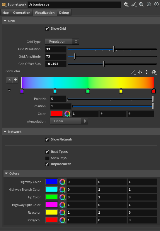
This update introduced “road levels”. Each point in the network has various attributes. One of them is the road type (intersection, tip, ray, highway, highway branch, or bridge). However, I want more than just 2 types of roads. I switched the highway branch and highway to determine how many branches off the main avenues a road is. A main avenue is a level of 1 and the level goes up each time the network branches. You can see this in my road levels visualization on the right.

v0.6.04 03-24-25
Once the tool is completed, the final product will be an HDA (Houdini Digital Asset). Basically, it condenses the entire algorithm into a single node. I had been avoiding this before, using different attribute wrangle nodes to modify the settings. In this update, I reworked the entire layout. Everything is now inside a subnet (which can be converted to an HDA. This means all the settings are in one place and I can make everything more consistent. I also focused on visualization. As I’ve stated in the past, a significant amount of coding is just being able to see what I’m doing and the effects of the code. A variety of visualization options helps significantly. It also allows the user to see their effects. I’m still deciding how much of it will be accessible to the user, but for now I’m giving complete control. I also added some noise to the painted population to add variety.


v0.6.02 11-13-24
This update was pretty small. I created an input for terrain. Currently, it’s just a Perlin noise, but eventually I plan to get terrain data from a height field and inform the network information derived from height data.

v0.6.01 11-08-24
To represent the radial street pattern, I added a feature that allows the artist to change the city center location and how many radial branches the city starts with. Previous, the starting geometry was a single line that would be reflected and then added upon, but now there is a script to generate a specified number of lines radiating out from the centerpoint.

v0.6.00 10-22-24
For this version I worked at integrating the ability for an artist To paint in data layers. In this case the left map below is a population density map that’s compounded with the perlin noise that was there before. The right map is for a checker-style street grid, which just sets the population influence to 0.


v0.5.06 10-17-24
In this version, the population sampling is more advanced. Previously the branch tips sample population density by shooting a fan of rays out and samples at the ends. Now, each ray is divided by new points at equal intervals. It samples from each point, then weights them by the inverse of the distance and sums the values up. The ray with the highest sum is chosen to influence the direction. I also spent some time cleaning up the code, making it run more efficiently.

v0.5.04 10-17-24
In this update, I made the main highway start going from both directions, This creates a more organic road network, as opposed to the very linear previous versions. While it seems like a small change, it required me to rewrite quite a bit of code, overhauling how it initializes the first few points.
v0.5.03 10-16-24
I added an attraction for the roads towards population centers (currently represented by a perlin noise. The top image is the previous version only using a random value to turn the roads. The second image has no random turning, only a weighted influence from population maps. I also created more efficient point attributes; now using “type” to cover everything instead of a separate attribute for each. Previously the types were highway (blue), highway branch (Cyan), intersection (magenta), and ray (yellow). Whether the point is a branch tip or not is stored separately and colored green. My next plan is to integrate water/invalid areas, different road patterns, or terrain constraints.


v0.5.02 10-15-24
This is demo footage where I show off the road branching algorithm, how it can be bent randomly, and how I can represent a 2d image (Perlin noise at the moment) as a grid. All these effects are achieved primarily through “point attributes”, which store data like whether it’s a branch tip, a population density statistic, or the height of the terrain. However, it becomes a lot of information at higher iterations. I believe this is part of why it gets quite slow. I plan to eventually go back and have the program “clean up” behind itself, only storing data that might be needed later